


| The
Radiosity problem has been originally proposed as a finite element problem,
which is solved by tesseletating uniformly (in the logical space) the
input surfaces. Although, one can increase the accuracy of the solution by
subdiving surface more and more, still some problems exist that are very annoying
to the human eye. These problems are closely related to the uniform way of
subdivision, i.e. they are presented in the form of aliasing artifacts.
These are: (a) light leakage, (b) shadow leakage and (c) staircase effect.
Discontinuity meshing is a way of achieving high numerical and visual accuracy when performing radiosity computations and it was first proposed by Heckbert [1992] and Lischinski et al. [1992,1993]. Instead of subdiving surfaces in a uniform way, the whole environment is taken into account, in order to construct certain types of virtual discontinuity surfaces. The intersection of these virtual surfaces with the input surfaces will yield the discontinuity segments which are used to guide the subdivision process. In a polygonal environment, two different types of virtual discontinuity surfaces arise: (a) VE event (planar surface) which is formed by a vertex and an edge of the environment and (b) EEE event (quadric surface) which is formed by three edges of the environment. The former surfaces are easier to handle and fortunately, they correspond to most annoying artifacts (D0, D1 discontinuities). |
|
|
|
|
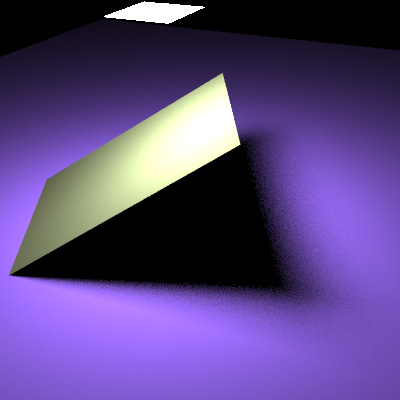
In general, the shadow discontinuities caused by the occluder on the floor are D2 (i.e. the second derivative of the radiosity function is discontinuous). Of course we must not ignore the discontinuities D0 caused by the occluder intersecting/touching the floor. (Image rendered with Phos) |
|
|
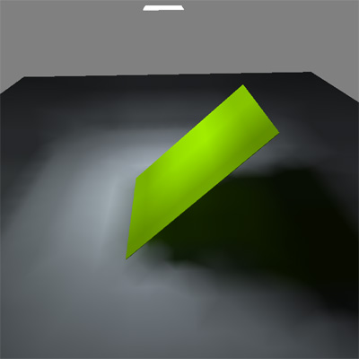
Here, the occluder rotates and some of its edges become coplanar with some of the light quadrilateral edges. As a consequence, two or more D2 discontinuities unite to yield discontinuity D1, which one has to deal with, because of the eye being very sensitive to this kind of discontinuities. (Image rendered with Phos) |
|
|
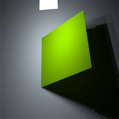
Light leak in the lower left corner of the surface gives the illusion of the surface floating over the ground. Discontinuity meshing will help in modeling correctly D0 and D1 discontinuities. (Image rendered with dRad) |
|
|
Even in high detail, one can observe the staircase effect in the shadow boundaries on the floor. (Image rendered with dRad) |
|
|
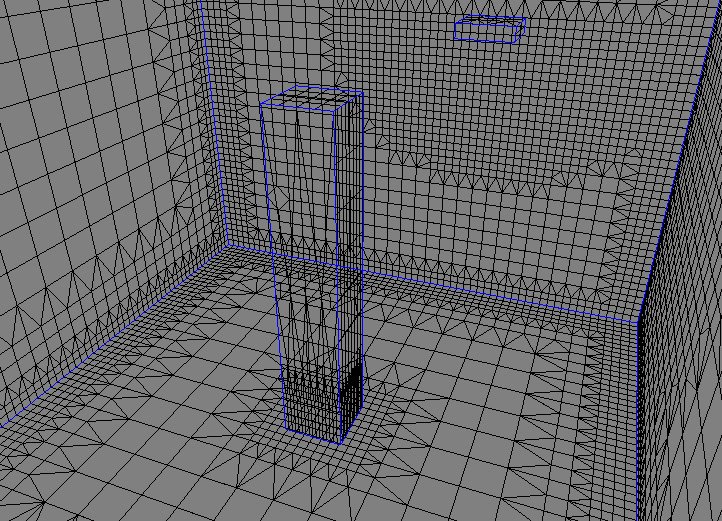
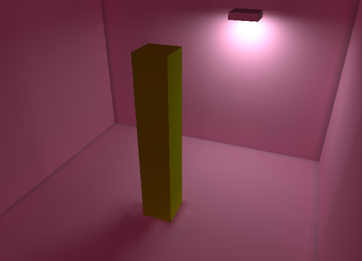
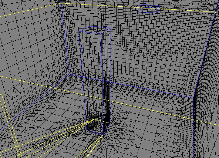
Here is a typical example of meshing with a small room, a box centered in the room and a rectangular light on one side of the room. Notice the higher subdivisions near the light and near the corners of the room in the first (wireframe) image. Also, notice the lower part of the box along with the part of the floor under the box where the subdivision is higher than elsewhere. This subdivision is (mostly) based on an upper bound of the form factor between the source and receiver surfaces. The emitting power of the source is also taken into account. In the middle image, one can see the flat rendering of the room while in the last image, the radiosity has been smoothed on image space using gouraud rendering. Notice, in this last image, the presence of light leaks under the box which gives the impression of the box floating over the ground. (Images rendered with dRad). |
|
|
|
|
|
|
|
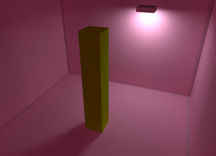
Now, the same environment as in the previous paragraph, has been simulated using discontinuity meshing. Only, the VE events formed with either a vertex or an edge of the rectangular light have been taken into account. The discontinuity segments are shown with yellow color over the subdivided input polygons. The "strongest" ones appear on the shadow of the box, near the box, and on the back wall (VE event with vertex and edge chosen from the same polygon). Notice how the subdivision changes from uniform subdivision to subdivision along the discontinuity yellow lines. discontinuities. In the middle image, one can see the flat rendering which is significantly improved and in the last image, the results have been smoothed using gouraud rendering. No more light leakage! The box seems to stand correctly on the ground. (Images rendered with dRad). |
|
|
|